
Agisoft PhotoScan (commonly known as PhotoScan) is a professional tool for a photogrammetry pipeline. It performs photogrammetric processing of digital images and generates 3D spatial data. Agisoft Photoscan is the dominant photogrammetric software on the market, being used by a range of professions, from archaeology, cartographers to creators of virtual worlds and game developers. Unlike Visual SfM, it contains a complete program to numerous specific tasks and different types of data, and, as a novice to photogrammetric software, was easily managed, with an efficient workflow system.
Digital Artefact: Agisoft PhotoScan – Structure from Motion/Photogrammetry Software
Digital Tools Used: Digital Camera, Agisoft
Skills Needed: Searching for software online. Basic skills in downloading software and installing them onto computer. Workflow system. Understanding of different file formats.
Level: Intermediate with support. I followed several excellent online tutorials in written and video format.
Licence: Professional and Standard (commercial) and Educational (non-commercial)
Possible Use for Community Archaeology Project: Create complete 3D models of artefacts, georeferenced orthophotos, export of texture.
Using Agisoft PhotoScan
Photographs
As with Visual SfM, a number of photographs must be taken completing a 360 degrees of the object to be scanned. In this instance, another Ogham Stone from Burnham House. Forty four images in total. This is not a high number for 3D data map, but at this point, I was more interested in learning the process. For more accurate results, more photographs would have to be taken.
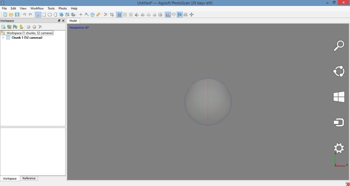
Agisoft PhotoScan Interface
Below is a screen shot of the Agisoft PhotoScan interface. There is a toolbar on the top, side window on the left, and the main model area in grey.
Preferences
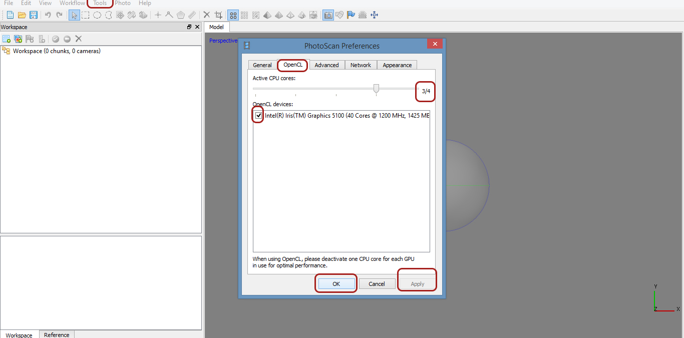
Before starting, the preferences can be changed. This is not necessary, but could improve the quality of the final data set. You can utilize your graphics card to compute all the algorithms.
Go to Tools > Preferences> OpenCL > Text at the bottom of the dialogue box suggests you deactivate one CPU core for each GPU in use for optimal performance. Select the box beside the graphics card. Lower the Active CPU cores one bar. In this instance, from 4/4 to 3/4.
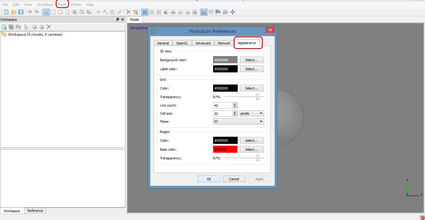
You can also change the background colour to a darker grey. This may be helpful if your points are a light colour and difficult to see. Go to Tools > Preferences > Appearance > Change the background colour.
Workflow
In the Agisoft Photoscan software I worked through the workflow system. Workflow is the series of activities that are necessary to complete a task; each step in a workflow has a specific step before it and a specific step after it, with the exception of the first step [Rouse 2016]. The workflow can be different, depending on the final model you want, and how you are going to use the model. For research purposes, you may only need a mesh, but for visuals and animation, you may need texture. The speed at which the software will process the data set, and the resultant 3D model, will depend on how you want to use the data after you have created the model. This is important as you can set various levels such as accuracy and quality. This will be discussed in more detail as I go though the steps to creating a 3D model of an Ogham Stone.
In Agisoft Photoscan, it is a linear workflow. I will be working with five basic steps:
- Adding Cameras: The first step is initiated by an outside event, in this case the adding of photographs, or cameras. This step uploads all of your images into the Agisoft interface
- Align Photo: The second step is aligning the photos or cameras, to create a sparse point cloud. The computer program compares the pixels in your photos to find matches and estimates the camera locations; these are a series of multidimensional points along the surface which give all the necessary information, to render the data properly, that is, to recreate a physical object in 3-dimensional digital space. A point cloud is a set of data points in some coordinate system; in a three-dimensional coordinate system, these points are usually defined by X, Y, and Z coordinates, and often are intended to represent the external surface of an object 8. For example, in GIS, geographic information systems, the X and Y can represent ground coordinates such as latitude and longitude, and the Z can represent an elevation. The sparse cloud will contain a certain amount of points.
- Dense Cloud: In step three, we will create a dense point cloud. This will have much higher number of points, or spatial data; therefore having much greater detail. Based on the estimated camera positions the program calculates depth information for each camera to be combined into a single dense point cloud [Agisoft 2016]. With an accurate clean sparse dense cloud, this process can be carried out much faster and with better results.
- Build Mesh: The fourth step is building a mesh. After dense point cloud has been reconstructed it is possible to generate a polygonal mesh model based on the dense cloud data [Agisoft 2016]. The 3 coordinates X,Y,Z, are connected into a triangular face, which combine seamlessly to produce a continuous mesh over the surface of your model. A typical final photogrammetric product is the polygonal mesh, which can be then used for a range of research purposes and/or used in other software programs such as Blender, Maya, SketchFab. However it is possible to go a step further and add texture and colour.
- Build Texture: as stated previously, for gathering data sets it is not necessary to build texture, but it will create a photo-realistic 3D model. If you are using the model for animation purposes, creating texture will add to the effects.
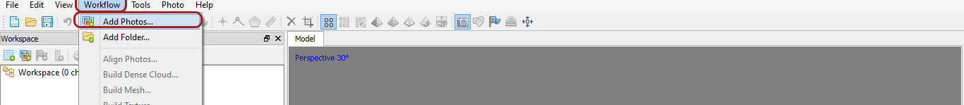
Step 1: Add Photos (cameras)
There are two ways you can upload photos to the software interface.
- Workspace > Add Photos
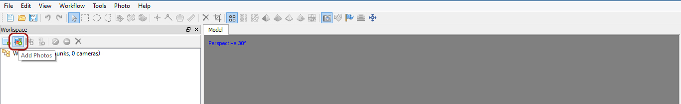
2. Workflow > Add Photos
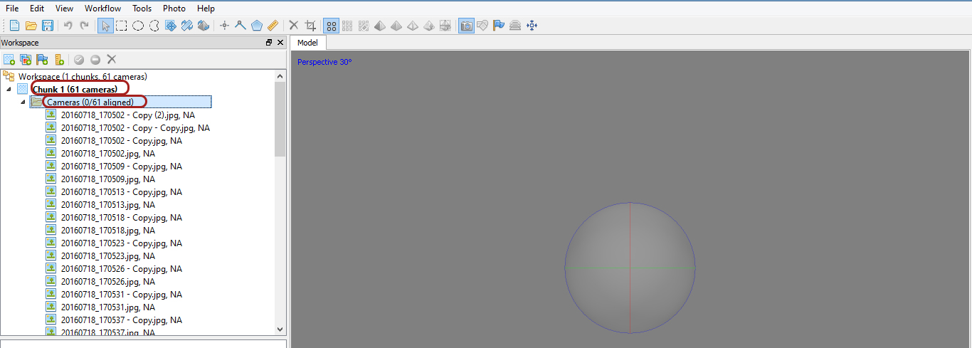
Select All > Open or Drag and drop images into workspace.
You will see the following in the Workspace area:
- Workspace refers to your workflow in progress.
- Chunk refers to one lot of photos. It is possible to work with 2 or more chunks. This can be used when you want to scan both ends of an artefact. In my case its not possible because the stone is in the ground.
Cameras (o/61 aligned) is the number of photos that are added, that points will be processed from.
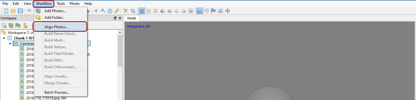
Step 2: Align photos
Once all the photos have been added, I clicked on Workflow and selected align photos
Workflow > Select Align Photos. This will open the Align Photo dialogue box.
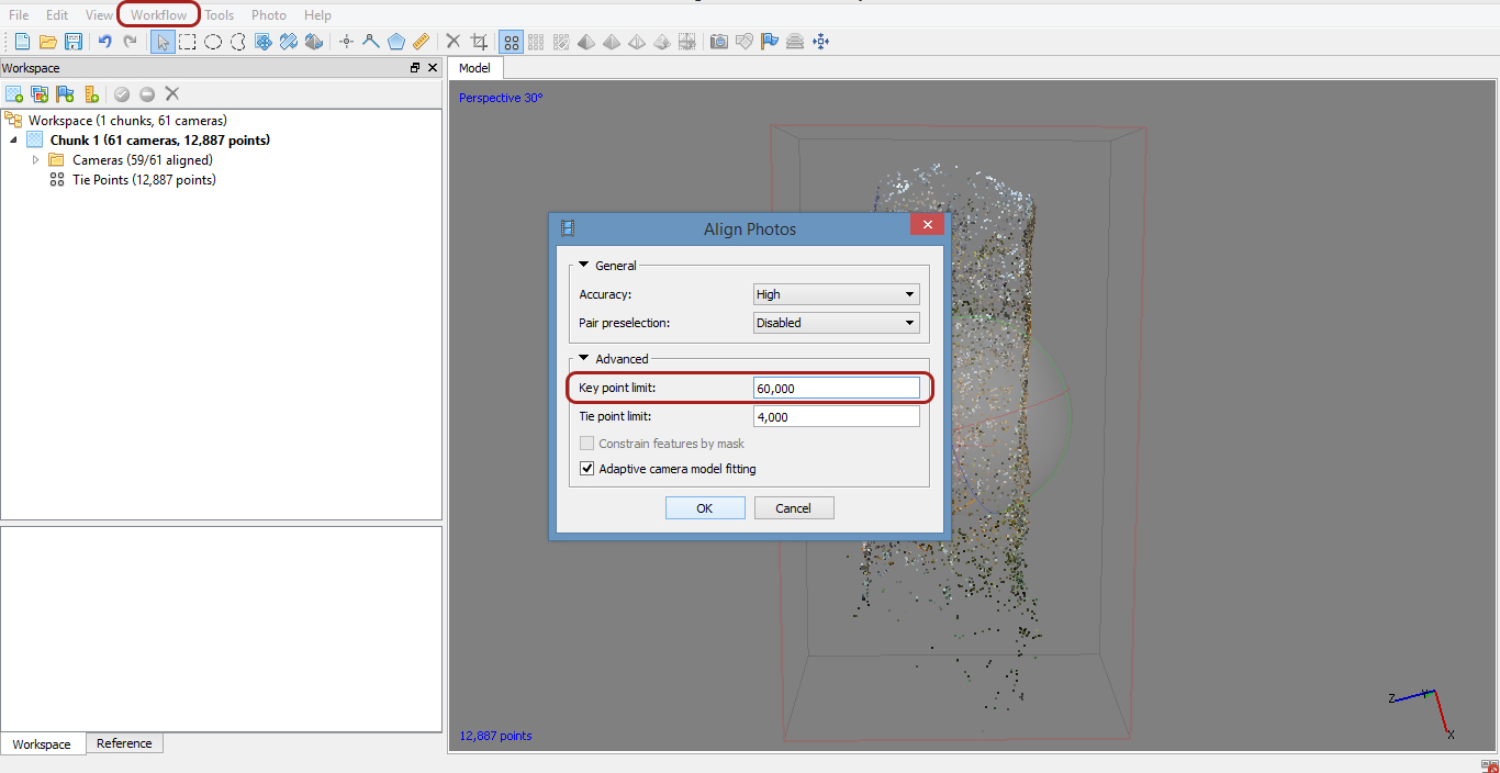
I had several choices to make, depending on the quality of your photos, the quality of output I want, and the speed at which the process takes. The higher the accuracy is set to, creates a higher point limit, and the longer the process will take.After selecting high, I then clicked on Advanced. In order to shorten the process, I started at key point limit of 40,000, and selected OK.
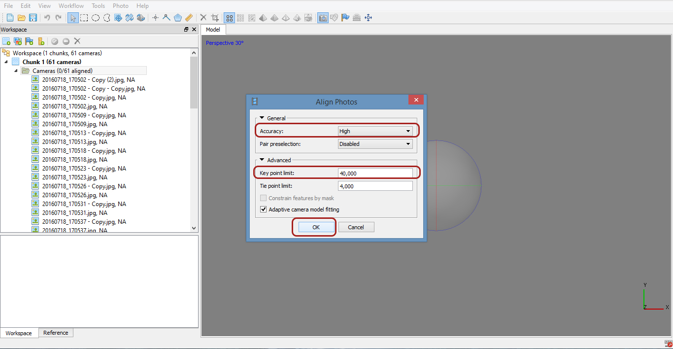
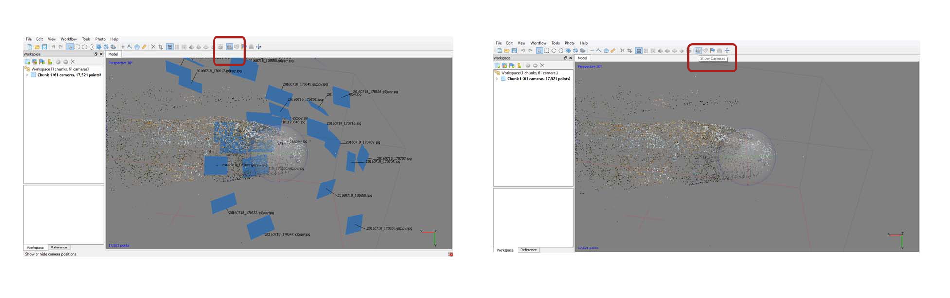
Matching the points and estimating the camera locations as the photos are aligned is the slowest part of the process, and can take up to 20 minutes, depending on the quantity and quality of the photos. When the process is finished you will see the sparse dense cloud of the model. The blue planes are the camera positions, the dots are the tie points – unique tracking points identified by the software. You can enable/disable the cameras to get a better view.
Cameras On / Cameras Off
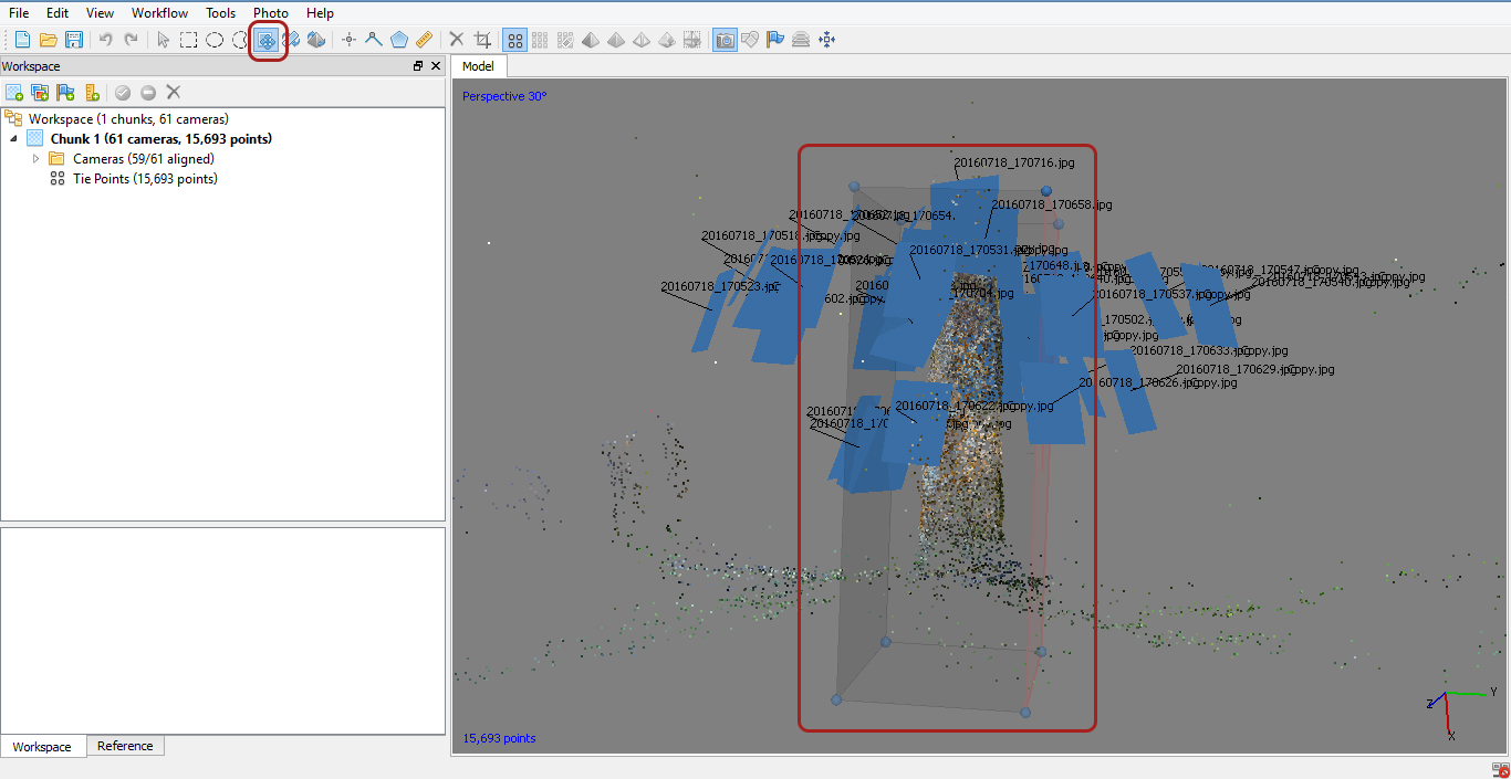
Adjust Region
Before moving onto the next step, it is worth cleaning up the model and re-running the process again. There are a few different steps I can take to remove extra points. Firstly, I can re-size and adjust the box around the model. This box is called a region. The software will only configure the points within the region box, so by readjusting it, we are cutting out multiple tie-points that we do not need.
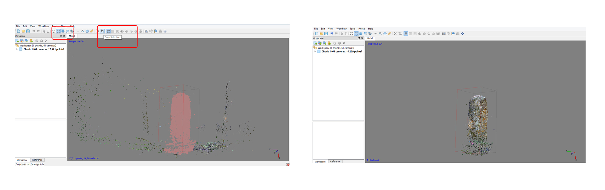
Cleaning the Model
It is important to clean around the model, to get rid of any unnecessary extra background points. This allows the software to create a better image and rendering, and also speeds up the process. You can do it 2 ways:
- Select the points you want to delete and press delete on keyboard.
- Select the points you want to keep and select crop on the toolbar.
Go back to navigation tool, zoom in and delete points you don’t want.
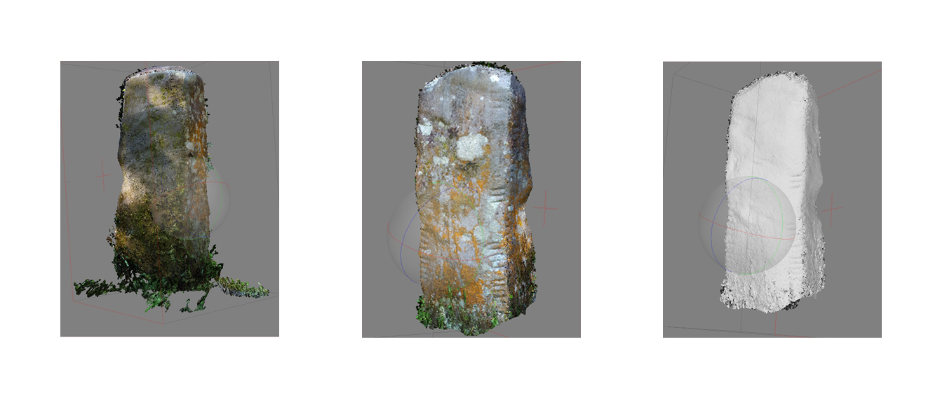
For a higher resolution, I repeated this step by re-aligning the photos again. I repeated the steps mentioned above, that is, Workflow > Align Photos, but this time, set the key points to 60,000.
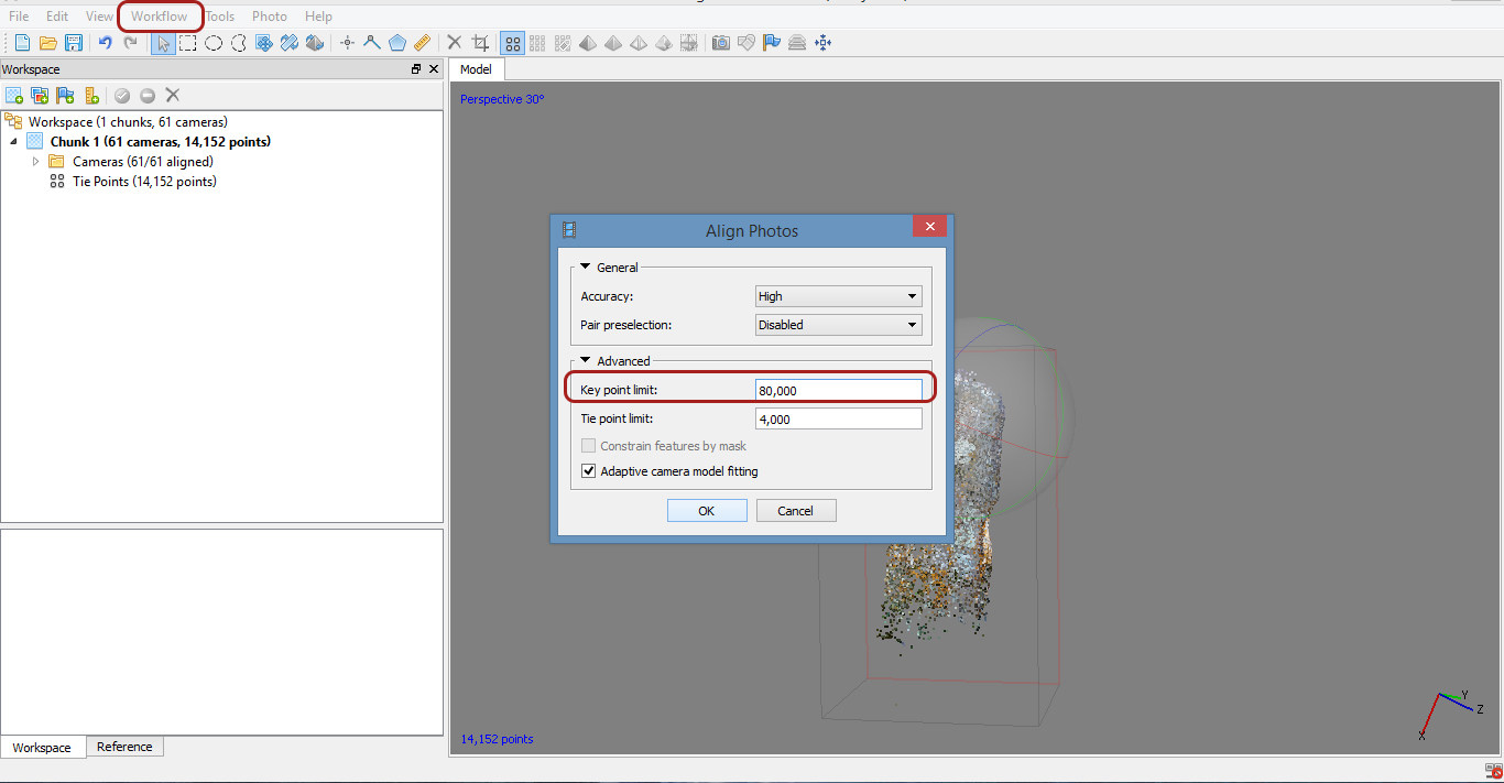
After this process was finished, I repeated the step for a third time. I cleaned up the model by deleting points, and readjusted the region box. I increased the key points to 80,000 and ran the process again.
Below are three images of the model. It seems like a long-winded way of working the process, but it is actually shorter than using the 80,000 key points straight away. In a scan with this few photos, there might not be much of a difference, but if using a larger quantity of photos, there will be.
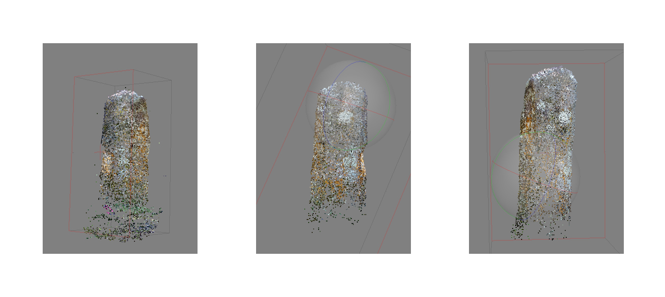
Model aligned at 40,000, 60,000 and 80,000 key points
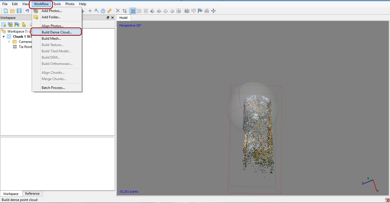
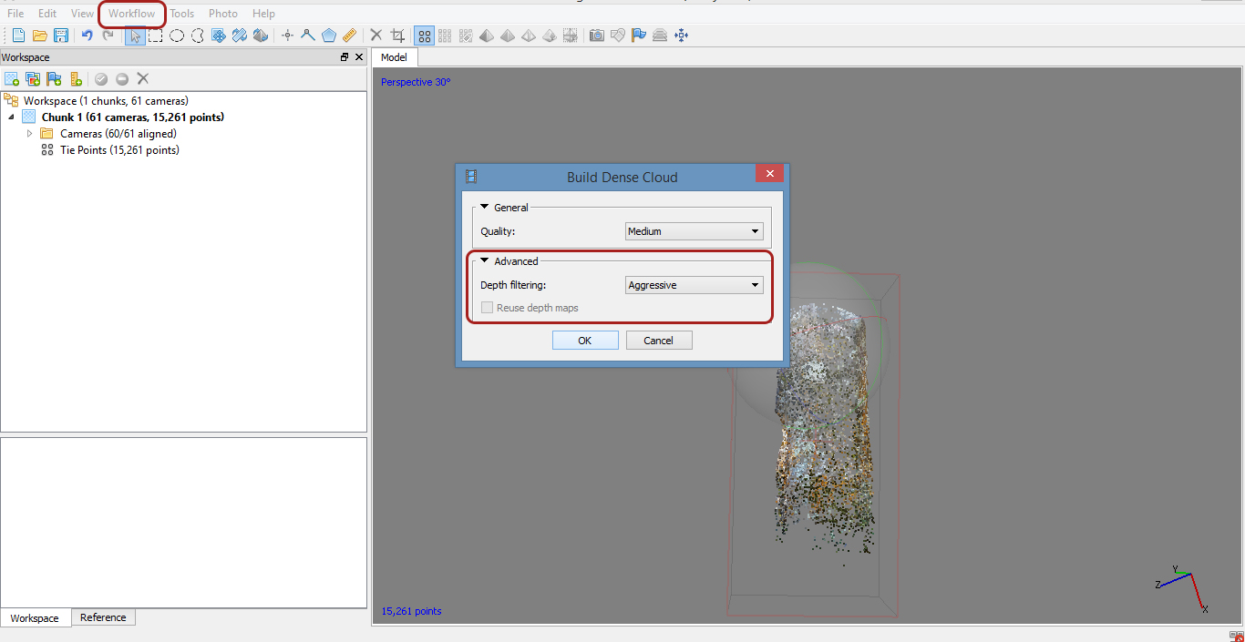
Step 2: Build Dense Cloud
Building a dense cloud will further improve an build more points to create a better polygon mesh. Before starting this step, it is worth checking again to see if the model needs more tidying up. I zoomed in and out, around the model, checking for more stray points and deleting them. Then click on Workflow and select Build Dense Cloud
Workflow > Build Dense cloud
As with the process for the alignment of the photos, I had multiple choices, when building the dense cloud. Ultra-high takes the longest to process, and isnt necessary unless you have a lot of data, and really high quality sharp images. Low takes the shortest amount of time. I selected medium. I left the depth field at aggressive. This is useful if your images are not of the highest quality. If they are, you can select medium. Select OK, and then let the process run. It can take several minutes.
After the dense cloud has been created you can see it by clicking on the dense cloud buttons.
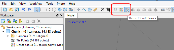
Below are the three types of data currently available to view. Sparse Cloud or Tie-points, Dense Cloud and Dense Cloud Classes.
Step 3: Build Mesh
Build mesh, is the creation of a polygonal mesh model, based on the dense cloud data. Before moving onto step 3, it is worth tidying up the model again. If there are points floating around, the mesh will connect these points. The cleaner the model is, the more accurate and precise the mesh will be. It is better to take the time and create a good model than have to repeat the whole process again, because of stray points in the mesh.

After clicking on the Workflow menu, I selected Build Mesh. This opened the Build Mesh dialogue box. There is not much you need to change here except the polygon count. This is number of faces in the resulting mesh, based on the number of points in the dense cloud. 500,000 works well, especially if you are going to use your data set in 3D software such as Maya. Interpolation is the default mode, this makes an effort to close any gaps in the mesh, if there is an area of little or scant point. I then selected OK.

When the process is complete, the 3D model icon, in the shape of a pyramid, can be seen in the Workspace pane. On the main toolbar, there is now a selection of new icons, again, the pyramid. I clicked on these to view the 3D Model that has now been created.
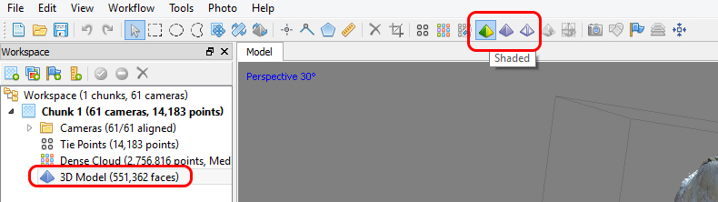
Shaded / Solid / Wireframe

If there is a hole or gap at any point on the model, it could be because of two factors:
- There were photos or tie-points missing.
- There was enough photos, but the area was too similar, and the software couldn’t find enough unique points.
At this point you can export the model, if that is all the data you need, or you can go onto Step 4 and Build Texture.
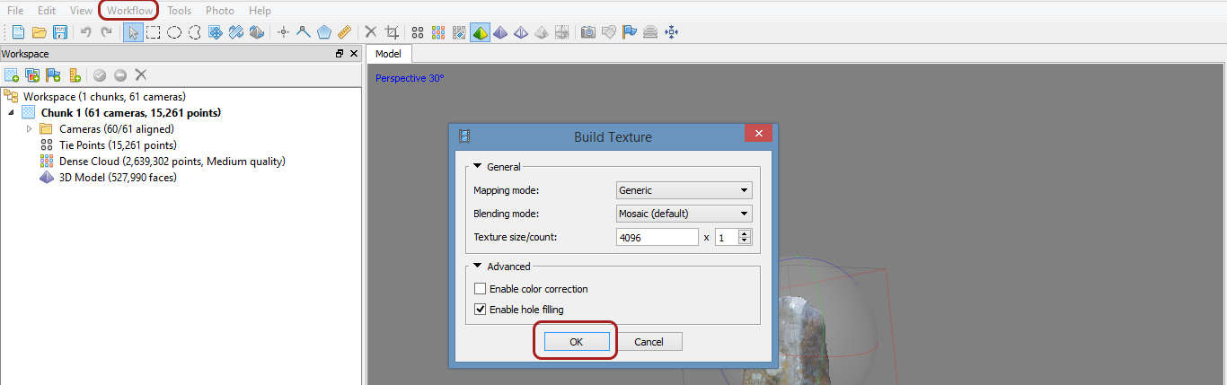
Step 5: Build Texture
The Texture data collected from Agisoft can be exported separately from the 3D model for use in other software such as Maya. There are different mapping modes, depending on the future use of your outputted data. It is important to remember that the lighting in a texture 3D model is not real lighting, but purely the colour of the texture, at the time the photographs were taken.
To complete this step, I went back to my Workflow Menu and selected Build Texture.
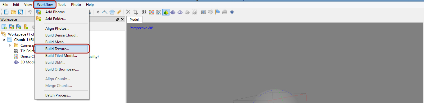
As stated above, there are several options depending on future use of texture. I was not looking to save the texture as a separate file, but I wanted to understand the process.
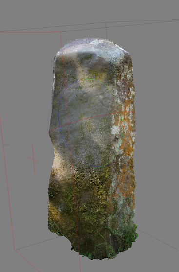
Below is an image of the model with a texture layer. As mentioned previously, the texture makes for a better looking model, but for the purpose of the Ogham in 3D project, it is not necessary.
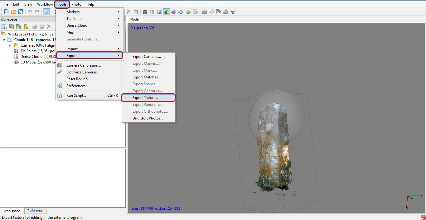
I exported the texture data file for possible use in the future. I clicked on Tools, in the top main menu, and then export, and export texture. A dialogue box will appear asking where to save the file. Export the texture data as a tiff or png, not as a jpeg as its a destructive format. Select OK.
Step 6: Export Model
To export the texture go to the model in workflow right click export model – select where to save – prompted with a dialogue box – export as a tiff or png, not a jpeg as its a destructive format – click OK.
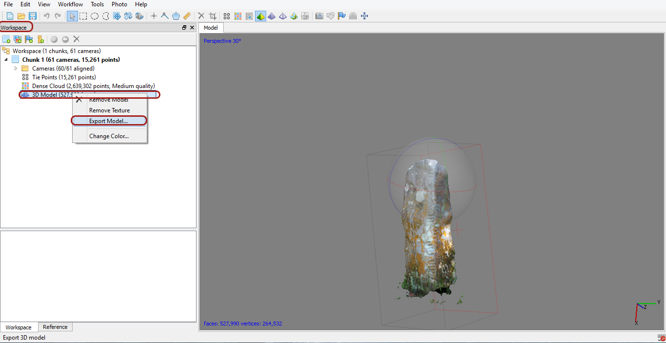
I saved the data of the 3D model as a .ply file. A PLY is a computer file format known as the Polygon File Format or the Stanford Triangle Format. It was principally designed to store three-dimensional data from 3D scanners.

For the Ogham in 3D project, the community group are emailing the files to Gary Devlin (The Discovery Programme), and Nora White (DIAS). The files are uploaded to MeshLab, an open source system for the processing and editing of unstructured 3D triangular meshes, and SketchFab, a web platform to publish, share and embed interactive 3D files, and finally onto two websites, the Ogham in 3D website and the CorcaDhuibhne3D website.
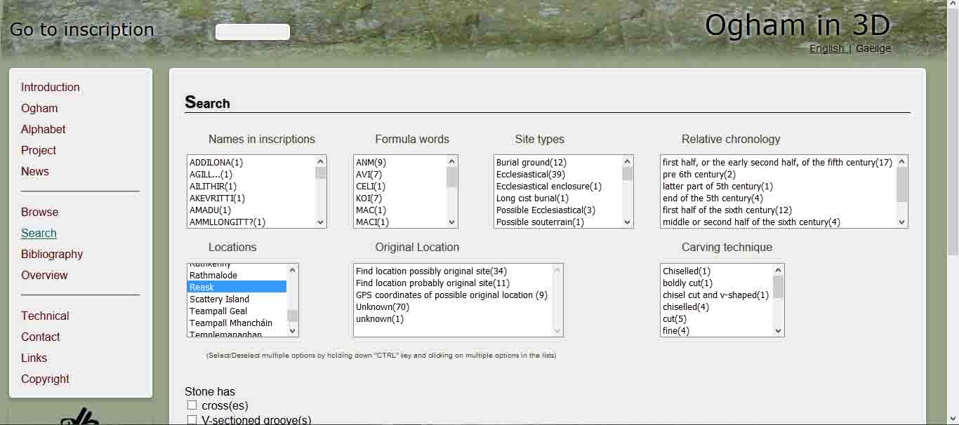
Screenshot from Ogham in 3D website showing search options
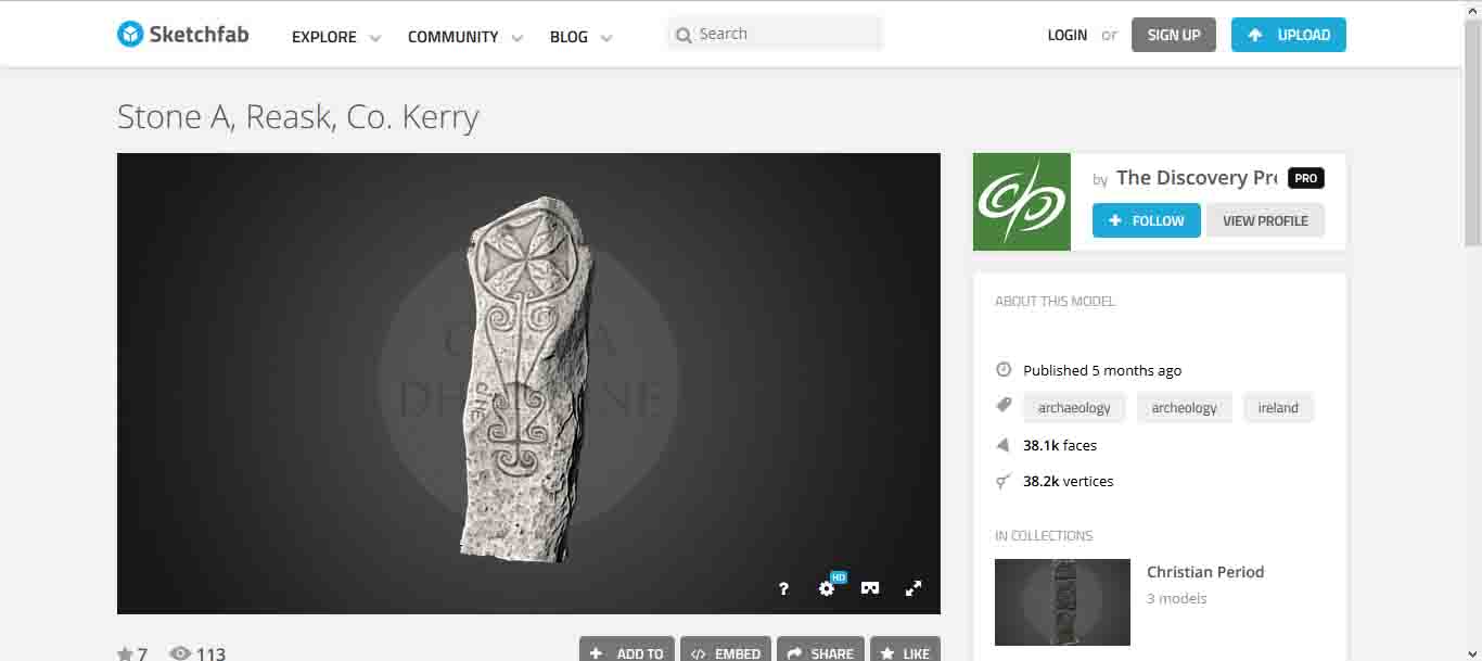
Screenshot of The Discovery Programme on SketchFab showing Ogham stone from Reask, Dingle Pensinula, Co. Kerry
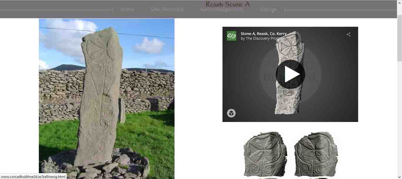
Screenshot from Corca Dhuibhne 3D new website showcasing all the Ogham Stones in Dingle Pensinula. The above Ogham is from Reask.
Save
Save
One Comment